reposted from old NLG site...
Ok a good way to add a computer power supply to a Wms 40x
slot machine. Since the original lower Wms power supply is very problematic,
this allows a cheap "plug and play" computer power supply to be implemented
quickly and without hassle. This design allows easy addition/removal of a computer P.S.
to the existing Wms harness. If this new computer P.S. dies, within 2 minutes you
can install another. These computer power supplies are inexpensive and
easy to get online or at any local computer store. With this mod,
if you get the original Wms P.S. working,
the added Computer P.S. can be removed quickly (with only the added plug
to the original harness being left behind).
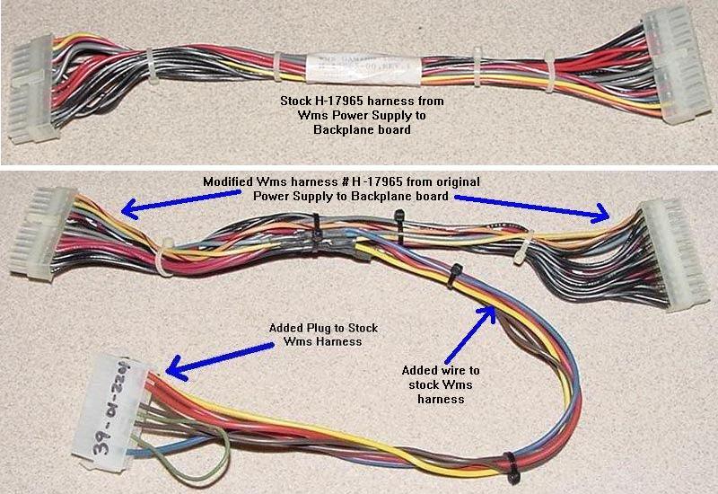
I modified the original Wms cable (#H-17965-0x) going from the
large 24 pin Wms power supply to the Wms back panel board.
Splicing in wires, and adding a connector for the new computer P.S.
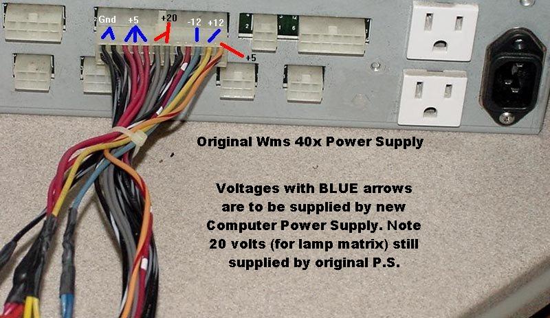
The new computer power supply will be replacing the
following voltages (originally supplied by the Wms switching
power supply). Any 250 watt or higher ATX power supply
should be able to supply this power. I'm using the "old style"
ATX with the 20 pin main connector. (The newer 24 pin
ATX power supply can be used too, just need to cut off
four pins. But why do that, just get the original ATX style
power supply.)
Power needed:
+5 vdc at 10 amps
+12 vdc at 5 amps
-12 vdc at 1 amp
Parts Needed:
(1) Molex connector housing#39-01-2201 (Mouser.com #538-39-01-2201)
(8) Molex connector pins #39-00-0041 (Mouser.com #538-39-00-0041)
(2) 1ft red wire
(2) 1ft black wire
(1) 1ft blue wire
(1) 1ft yellow wire
(1) 4" piece of green wire
(1) ATX Computer Power Supply (at least 250 watts or higher)
(1) foot 1/4" heat shrink tubing
Orignal H-17965 harness in Wms model 40x machines
Molex crimping tool (for adding the new pins)
I've been buying power supplies from Geeks.com and
like this one for $12. It's 400 watt and has two 12 volt
supplies (20amp and 12amp). This works great especially
if you run the upper dot power supply off this ATX power
supply too (the upper and lower 12 volts are segregated
with this power supply, one off the main 20 pin connector,
and one off the 4 pin peripheral connectors, which is kind of cool.)
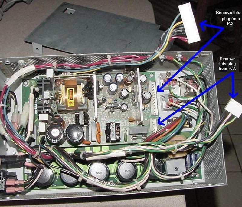
http://www.geeks.com/details.asp?invtid=AGS400&cat=PWRAs described above, remove the original lower power supply
form the slot. Then open up the existing original Wms power
supply and remove the two .156" modex connectors from
the switching power supply. Replace the cover and re-mount
the original Wms power supply.
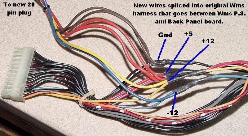
Using a soldering iron splice in two new red wires to the existing
Wms harness' red wire going from the power supply to the
back panel. Use heat shrink tubing for a clean insulated job.
This is +5 volts.
Using a soldering iron splice in two new black wires to the existing
Wms harness' black/gry wire going from the power supply to the
back panel. I use the two black/gray wires that are right next
to the three red wires (see pic below.)
Use heat shrink tubing for a clean insulated job.
This is ground.
Using a soldering iron splice in one new yellow wire to the existing
Wms harness' yellow wire going from the power supply to the
back panel. Use heat shrink tubing for a clean insulated job.
This is +12 volts.
Using a soldering iron splice in one new blue wire to the existing
Wms harness' blue wire going from the power supply to the
back panel. Use heat shrink tubing for a clean insulated job.
This is -12 volts.
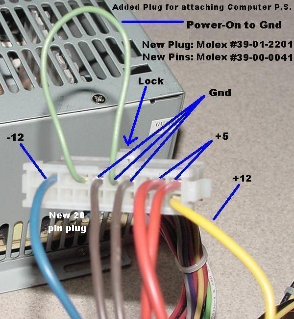
Now crimp new 39-00-0041 male Molex pins to the ends of
my new wires, and insert them into the 39-01-2201 connector.
This connector will mate to the new power supply. Be careful
crimping the pins, they are very easy to damage.
In addition, crimp pins to both ends of the green 4" piece of wire.
This goes into the new plug as the green "power-on" to ground
jumper (which allows the power supply to turn on without software
control).
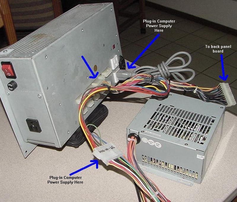
Install the new computer power supply inside the slot. Plug the
120v computer P.S. into the original Wms power supply (use the white
120v plugs near in the back of the power supply.
Mount the new power supply in the corner below/behind the
bill acceptor. Or maybe below the original power supply
(haven't tried that position yet.)
That's it!
Testing your new Computer Power supply.
----------------------------------
After making the above cable modifications, i like to
test the new rig. Unfortunately you really can't do this
outside of the slot (because the transformer supplies
voltage to the Wms power supply, and the new computer
power supply wants a "load").
So this is what i do:
Remove the I/O board and PCBA processor board
from the game, and set aside. Now i have a SMOKED
I/O board that i install. The board is already broken,
but the LEDs work. So with my broken I/O board
installed (and no processor board), i power up the
rig. All five LEDs should be ON. (the left side Fail LED
may or may not be on, but it does not matter.)
Now use a DMM and check the voltages coming out
of the Wms power supply 24 pin plug:
Pin 1,2 (blk/gray) = Gnd
Pin 3,4,5 (red) = +5 volts
Pin 6,7 (gray) = +20 volts
Pin 8 (blk/white) = -1 volts (sense, voltage varies, ignore)
Pin 9 (red/white) = +.5 volts (sense, voltage varies, ignore)
Pin 10 (blue) = -12 volts
Pin 11 (yellow) = +12 volts
Pin 12 (orange) = +5 volts
....
Pin 13-24 (blk/gray) = Gnd (entire bottom row)
Make sure all those voltages are good.
If you are missing +5, -12, or +12, then you did
something wrong with the new wiring (or your
new computer power supply is dead). Note the
20 volts is supplied by the original Wms power
supply (it is unregulated, goes through a bridge
rectifier, filter caps, and a fuse). If that is missing
you will need to check the bridge rectifier/fuse inside
the original Wms power supply box.
If the voltages are good, remove the test I/O board,
and install the two "good" boards.
And you're off and running!
------------
I tried some 200 watt power supplies, they seemed to work fine.
But I would still say that 250 watts is probably the lowest you
should go.
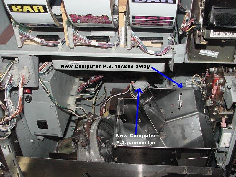
Picture of installed computer power supply below. Note I removed
the black vent sheild below the handle. The existing screws make
nice standoffs to hold the new computer power supply in place.
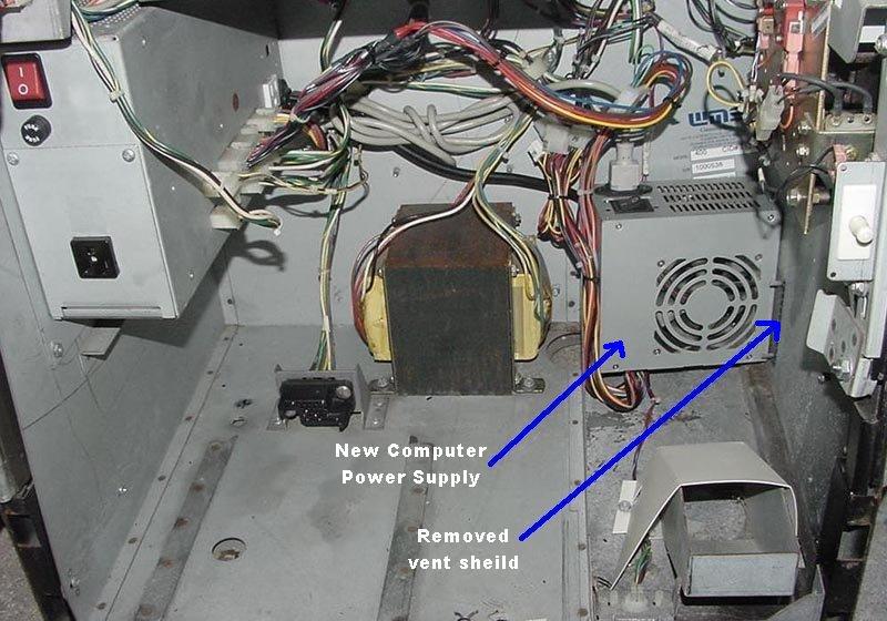
Computer power supply running in Perfect Match:
-------------------
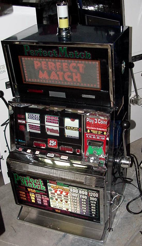
In this last posted picture; you seem to have a lot of room for the added PSU,
will take some snaps of our WMS's cabinet configuration in the morning, might
have to extend cabinet to make fit.
Yea it *looks* like there's tons of room with the hopper removed.
but after the hopper is installed, wow, there's like nothing left!
Might be room on the left back side (below the original P.S.)
Picture below...
-------------------------
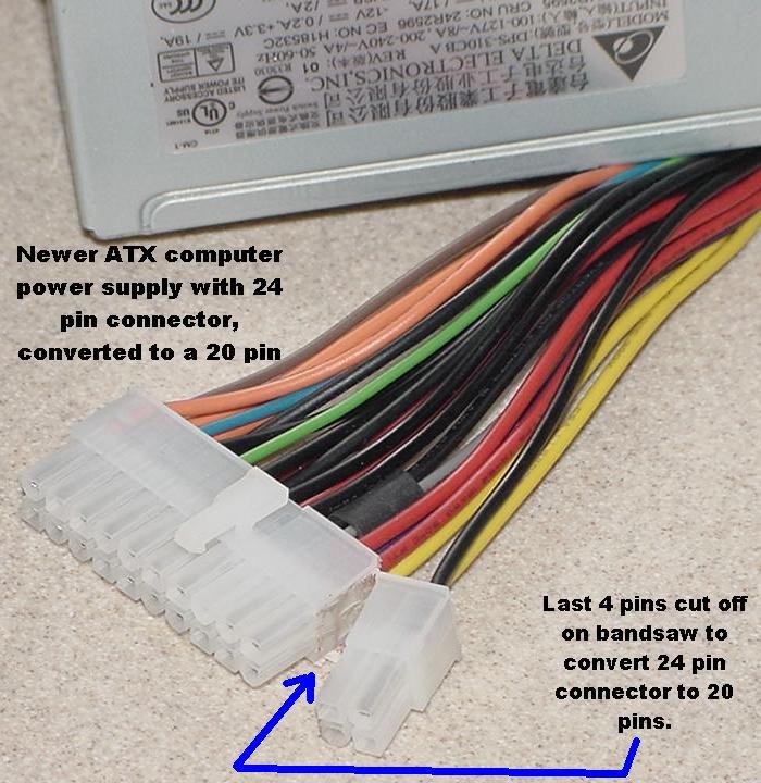
ATX Computer power supplies with 20 pin connectors are starting
to go away, replaced by ATX supplies with 24 pin connectors. These
can still be used, just the last 4 pins need to be cut off to fit the
20 pin connector used in the pictures above. (Alternatively you could
just by a 24 pin mating connector. But in my case I already had a
supply of 20 pin mating connectors to use.)
On the 24 pin computer power supplies, just use a bandsaw and
slice off the last 4 pins of the 24 pin connector. If you are careful,
there's no damage to the connector. See the picture below.


 Author
