Re-post from the old site...
Old tittle:
One new Computer Power Supply solves TWO dotmation P.S. problems
I did a post on how to replace the lower power supply with a new computer
power supply. And how to replace the upper dotmation power supply with
a new video game style switching power supply.
But why not just replace *both* the original upper and lower power supplies
with a single computer power supply?
This is actually pretty easy. If you read my post on how to implement a
computer power supply for a dead original lower power suppy, you
are 7/8th the way to using this same computer power supply for
the upper dotmation boards too.
Parts Needed.
---------------
(1) Amp/Tyco 4 pin connector housing #1-480-426-0 (mouser# 571-14804260)
(2) Amp/Tyco male connector pins #60620-1 (mouser# 571-606201)
(1) Extra long 8 pin Molex male header pins# 10-01-2270 (or 09-62-6104 or 09-52-3102).
(2) two inch long 18 gauge wire
(1) inch of 3/4" diameter heat shrink tubing
STEP ONE.
Implement a new 250 watt or higher ATX computer power supply
as a replacement for the original lower Wms power supply. In this
example I'm using an ATX P.S. with 12 volts at 13 amps and 5 volts
at 22 amps. That's probably about the bare minimum. (Ideally
12 volts should be at 15 amps.)
See the post below for instructions on how to implement
a computer power supply as a replacement for the stock
Wms lower power supply:
http://newlifegames.net/techforum/index.php?topic=7324.0STEP TWO.
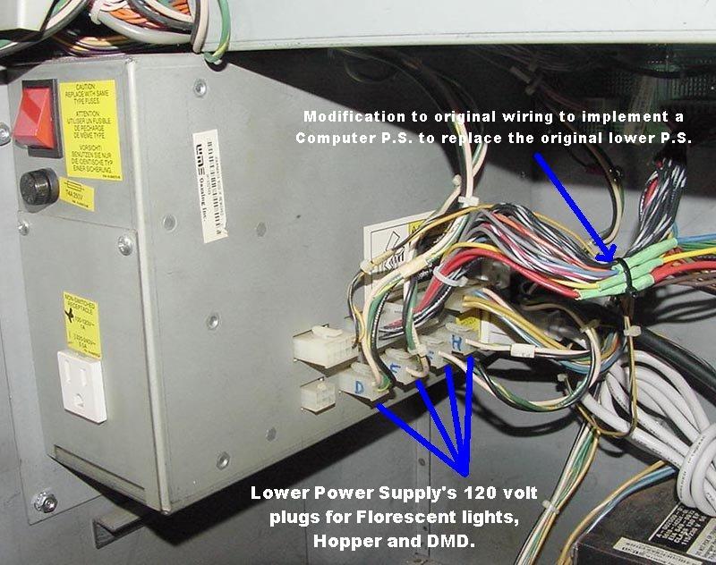
Find the 120 volt power connector for the upper dotmation
power supply. On the side of the lower power supply, there
are two rows of connectors. The bottom row has five connectors,
all with 6 pins. These are 120 volt connectors for powering the
two florescent fixtures, the hopper, and the upper dotmation
power supply. Find the connector labeled "P2", which is power
for the upper dotmation power supply. Remove this connector
and power up the slot. A "Dot Fail" message should appear
on the red LED displays.
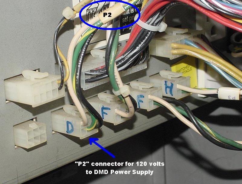
STEP THREE.
With the slot power turned off, cut off the 6 pin connector "P2"
with three wires (black, white, green)
going to the lower power supply. (This connector is the wiring
going to the upper DMD {dot matrix display} power supply.)
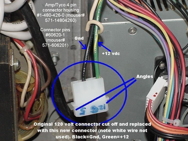
Using a Molex crimping tool, crimp new Amp male connector
pins onto the black and green wires. (Ignore the white wire, it
will not be used.) After the pins are crimped, insert them into
the new Amp connector housing as shown in the pictures below.
BE CAREFUL. The original green wire must mate with the
computer power supply's yellow (12 volt) wire. And the original
slot wiring black wire must mate with the computer
power supply's black wire. Don't screw this up or you can ruin
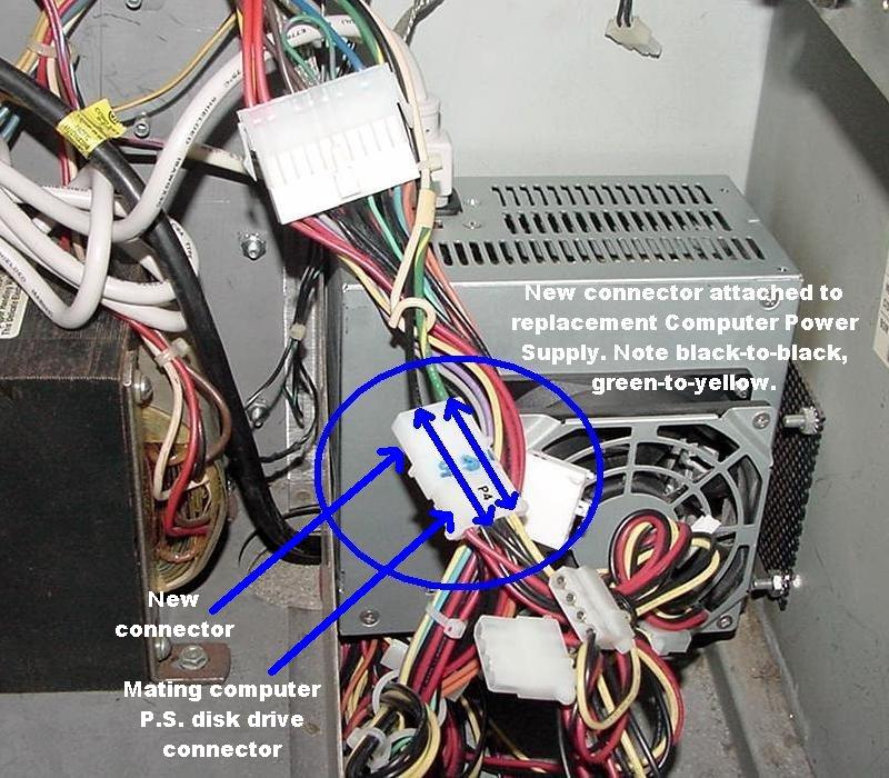
the DMD controller and DMD display. Plug this new connector
into one of the disk drive connectors on the newly installed
computer power supply.
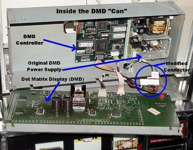
STEP FOUR.
Remove the top glass so access to the Dot Matrix "can" may be
allowed. Remove the top two screws and fold the DMD panel
down and out of the way. Notice the original Dotmation power
supply at the right - there are two .156" molex connectors
(one 5 pin, one 13 pin) at the bottom of the power supply.
Unplug these two connectors from the original Dotmation
power supply.
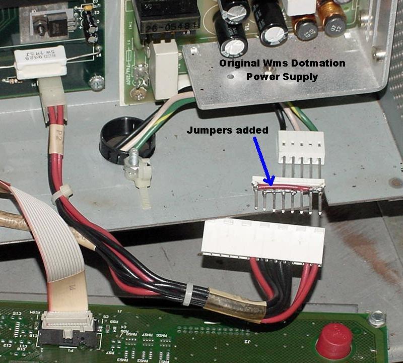
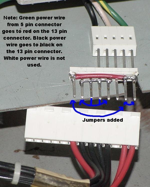
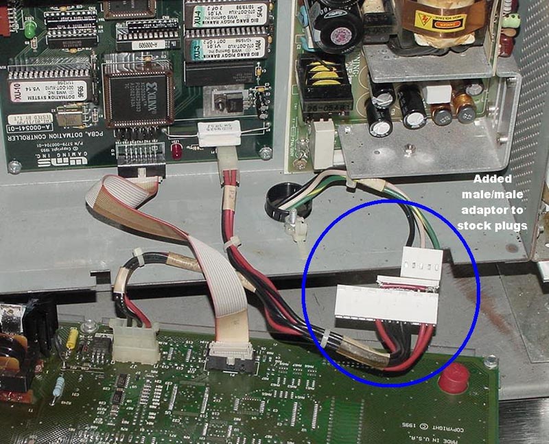
Using the extra long male 8 pin Molex header pins, modify it
with two pieces of wire. One wire will connect the two outside
+12 volt pins together. Another wire will connect the inside ground
pins are together (see picture below). Cut off three male
pins on one side of this connector too. (Again see picture
below.) Using a DMM set to continuity, make sure the +12 and Gnd
pins are not shorted, because that would be easy to do if your
soldering skills aren't up to par when attaching the wire to the
male/male adaptor.
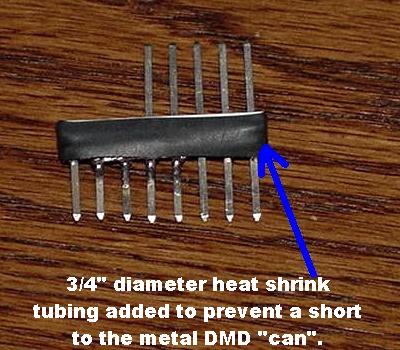
When done, it's a good idea to encase the jumper wires with
some 3/4" heat shrink tubing (or electrical tape). This would prevent
the male/male connector from shorting out against the Dot Matrix
metal "can".
Plug this male/male adaptor into the power connectors
for the DMD. (Again see two pictures below.) Note that the green
power wire mates to the red DMD connector wire, and the black
power wire mates to the black DMD connector wire.
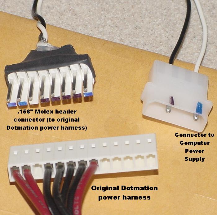
Another method to hook up the computer power supply
to the original Dotmation power harness. This uses a .156" Molex
header pin as the "mate" to the original Dotmation harness
(instead of the male/male .156" adaptor). This permanently alters
the original "feed" harness, and is shown in the picture below.
I use this technique when making a new power feed harness.
The main disadvantage to this is when feeding the assembly
into the metal dotmation "can", it has to be done "backwards"
(because the mating 8 pin connector is often too wide to fit through
the dotmation can wire hole).
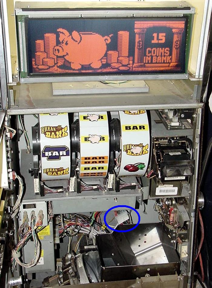
ALL DONE.
Power up the slot with the new computer power supply, and all
should work fine. Below is a Big Bang Piggy Bankin runing with
a 250 watt power supply for both the upper and lower power
supplies. The blue circle in the picture below shows the large
ATX style connector that is implemented for the lower power
supply.


 Author
